Thursday, September 24, 2009

Fighter Aircrafts In Indian Airforce

SEPECAT Jaguar IB


Date: 08 Feb 06
Size: 5 items
Views: 8778
Show URLs +
Get item URLs

SEPECAT Jaguar IM


The SEPECAT/HAL Jaguar maritime attack squadron (No.6) operates the IM variant. In 1996, a contract was signed with Elta to upgrade the maritime attack variant with the EL/M-2032 multimode fire control radar. Ten EL/M-2032 radars are to be supplied. The
Date: 08 Feb 06
Size: 9 items
Views: 7123
Show URLs +
Get item URLs

SEPECAT Jaguar IS


The SEPECAT/HAL Jaguar forms five operational squadrons in the IAF - four strike squadrons (No.5, No.14, No.16 and No.27) operating the IS variant and one maritime attack squadron (No.6) operating the IM variant. The IB dual seat trainer serves with the s
Date: 08 Feb 06
Size: 29 items
Views: 15989
Show URLs +
Get item URLs

MiG-21bis [Fishbed N] - Type 75


The MiG-21Bis (Type 75) is an advanced variant with further improved avionics indicated by the ILS antennae under the nose and on the fin tip. The airframe has a lifespan of 2,685 hours. Standard avionics include automatic radio compass, IFF and a Sirena-
Date: 08 Feb 06
Size: 19 items
Views: 7379
Show URLs +
Get item URLs

MiG-21Bison


The MiG-21 Bison is the most advanced variant with further improved avionics incl MFDs, HOTAS, RWRs and BVR Capability. The Bison was built upon the MiG-21 Bis variant
Date: 08 Feb 06
Size: 7 items
Views: 7829
Show URLs +
Get item URLs

MiG-21FL [Fishbed D] - Type 77


The MiG-21FL [Type-77] was the first major version to equip the IAF squadrons on a large scale. The aircraft was a development of the Type-76 which was operated in small numbers by the IAF. The FL was subsequently manufactured by HAL till the end of 1973.
Date: 08 Feb 06
Size: 18 items
Views: 8590
Show URLs +
Get item URLs

MiG-21M/MF [Fishbed J] - Type 96


The MiG-21M/MF (Type 96) is a Multi-role version with one R-11-300 turbojet with 13,688 lbs. of thrust. The aircraft has 4 pylons which can carry external fuel tanks, air-to-air missiles or twin barrel guns. Has a zero speed, zero altitude ejection seat.
Date: 08 Feb 06
Size: 6 items
Views: 4897
Show URLs +
Get item URLs

MiG-21bis [Fishbed N] - Type 75


The MiG-21Bis (Type 75) is an advanced variant with further improved avionics indicated by the ILS antennae under the nose and on the fin tip. The airframe has a lifespan of 2,685 hours. Standard avionics include automatic radio compass, IFF and a Sirena-
Date: 08 Feb 06
Size: 19 items
Views: 7379
Show URLs +
Get item URLs

MiG-23UM [Flogger]


The MiG-23UMs , the two seater variants of the Ground Attack and Interceptor units will have a continued innings, thanks to their role as type-trainers with the MiG-27 Units.
Date: 08 Feb 06
Size: 7 items
Views: 3923
Show URLs +
Get item URLs

MiG-27M [Flogger] Bahadur


Date: 08 Feb 06
Size: 14 items
Views: 8102
Show URLs +
Get item URLs

MiG-29 [Fulcrum] Baaz


The MiG-29 forms three operational squadrons (No.28, No.47 and No.223) in the IAF. A fourth squadron was expected to be raised, however plans for that have been scrapped. IAF MiG-29s have had their share of technical problems, since its induction in 1986.
Date: 08 Feb 06
Size: 27 items
Views: 23074
Show URLs +
Get item URLs

Dassault Mirage 2000H/TH


Known as the Vajra (Divine Thunder) in the IAF, the Mirage 2000s form two operational squadrons, No.1 Tigers and No.7 Battle Axes. The aircraft have been upgraded locally, with new EW (Electronic Warfare) and attack systems. HAL units in Bangalore and Kan
Date: 08 Feb 06
Size: 24 items
Views: 21305
Show URLs +
Get item URLs

Sukhoi Su-30K/MK-1 [Flanker]


The first deliveries of Su-30MK-1s arrived in kits at Lohegoan AFB in March 1997, where they were assembled and were formally inducted into the No.24 Squadron on 11 June 1997 by the then-incumbent Prime Minister, Inder Kumar Gujral. Ten Su-30K aircraft, w
Date: 08 Feb 06
Size: 20 items
Views: 12823
Show URLs +
Get item URLs

Sukhoi Su-30 MKI [Flanker]


In mid-2002, ten Su-30MKI aircraft were finally delivered in completely-knocked down kits to Lohegaon AFS. These aircraft were formally inducted into the No.20 Squadron on 27 September 2002.
Date: 08 Feb 06
Size: 33 items
Views: 25531
Show URLs +
Get item URLs

HAL ADA Tejas


The Light Combat Aircraft program is designed to come up with a mass replacement fighter to replace the MiG-21 Aircraft. The first prototype "TD-1" (Technology Demonstrator - 1 ) flew in January 2001. TD-1 was followed by TD-2, PV-1 (Prototype V
Date: 08 Feb 06
Size: 8 items (67 items total)
Views: 20945
Show URLs +
Get item URLs

This post was posted by Pradeep.M.K, III year, Aeronautical Engineering, Hindusthan Institute Of Technology

Laser propulsion


LASER PROPULSION is a form of Beam-powered propulsion where the energy source is a remote (usually ground-based) laser system and separate from the reaction mass. This form of propulsion differs from a conventional chemical rocket where both energy and reaction mass come from the solid or liquid propellants carried on board the vehicle.

TYPES:

ABLATIVE LASER PROPULSION

Ablative Laser Propulsion (ALP) is a form of beam-powered propulsion in which an external pulsed laser is used to burn off a plasma plume from a solid metal propellant, thus producing thrust. The measured specific impulse of small ALP setups is very high at about 5000 s (49 kN·s/kg), and unlike the lightcraft developed by Leik Myrabo which uses air as the propellant, ALP can be used in space.

Material is directly removed from a solid or liquid surface at high velocities by laser ablation by a pulsed laser. Depending on the laser flux and pulse duration, the material can be simply heated and evaporated, or converted to plasma. Ablative propulsion will work in air or vacuum. Specific impulse values from 200 seconds to several thousand seconds are possible by choosing the propellant and laser pulse characteristics. Variations of ablative propulsion include double-pulse propulsion in which one laser pulse ablates material and a second laser pulse further heats the ablated gas, laser micropropulsion in which a small laser onboard a spacecraft ablates very small amounts of propellant for attitude control or maneuvering, and space debris removal, in which the laser ablates material from debris particles in low Earth orbit, changing their orbits and causing them to reenter.

PULSED PLASMA PROPULSION

A high energy pulse focused in a gas or on a solid surface surrounded by gas produces breakdown of the gas (usually air). This causes an expanding shock wave which absorbs laser energy at the shock front (a laser sustained detonation wave or LSD wave); expansion of the hot plasma behind the shock front during and after the pulse transmits momentum to the craft. Pulsed plasma propulsion using air as the working fluid is the simplest form of air-breathing laser propulsion.

CW PLASMA PROPULSION

A continuous laser beam focused in a flowing stream of gas creates a stable laser sustained plasma which heats the gas; the hot gas is then expanded through a conventional nozzle to produce thrust. Because the plasma does not touch the walls of the engine, very high gas temperatures are possible, as in gas core nuclear thermal propulsion. However, to achieve high specific impulse, the propellant must have low molecular weight; hydrogen is usually assumed for actual use, at specific impulses around 1000 seconds. CW plasma propulsion has the disadvantage that the laser beam must be precisely focused into the absorption chamber, either through a window or by using a specially-shaped nozzle.

HEAT EXCHANGER (HX) THRUSTER

The laser beam heats a solid heat exchanger, which in turn heats an inert liquid propellant, converting it to hot gas which is exhausted through a conventional nozzle. This is similar in principle to nuclear thermal and solar thermal propulsion. Using a large flat heat exchanger allows the laser beam to shine directly on the heat exchanger without focusing optics on the vehicle. The HX thruster has the advantage of working equally well with any laser wavelength and both CW and pulsed lasers, and of having an efficiency approaching 100%. The HX thruster is limited by the heat exchanger material and by radiative losses to relatively low gas temperatures, typically 1000 - 2000 C, but with hydrogen propellant, that provides sufficient specific impulse (600 - 800 seconds) to allow single stage vehicles to reach low Earth orbit.

LASER ELECTRIC PROPULSION

A general class of propulsion techniques in which the laser beam power is converted to electricity, which then powers some type of electric propulsion thruster. Usually, laser electric propulsion is considered as a competitor to solar electric or nuclear electric propulsion for low-thrust propulsion in space. However, Leik Myrabo has proposed high-thrust laser electric propulsion, using magnetohydrodynamics to convert laser energy to electricity and to electrically accelerate air around a vehicle for thrust.


This post was posted by Arun Prakash.j , III year, Aeronautical Engineering, Hindusthan Institute Of Technology

Wednesday, September 23, 2009

TURBOFAN ENGINE

To move an airplane through the air, thrust is generated by some kind of propulsion system. Most modern airliners use turbofan engines because of their high thrust and good fuel ef. On this page, we will discuss some of the fundamentals of turbofan engines.


A turbofan engine is the most modern variation of the basic gas turbine engine. As with other gas turbines, there is a core engine, whose parts and operation are discussed on a separate page. In the turbofan engine, the core engine is surrounded by a fan in the front and an additional turbine at the rear. The fan and fan turbine are composed of many blades, like the core compressor and core turbine. and are connected to an additional shaft. All of this additional turbomachinery is colored green on the schematic. As with the core compressor and turbine, some of the fan blades turn with the shaft and some blades remain stationary. The fan shaft passes through the core shaft for mechanical reasons. This type of arrangement is called a two spool engine (one "spool" for the fan, one "spool" for the core.) Some advanced engines have additional spools for even higher efficiency.

How does a turbofan engine work? The incoming air is captured by the engine inlet. Some of the incoming air passes through the fan and continues on into the core compressor and then the burner. where it is mixed with fuel and combustion occurs. The hot exhaust passes through the core and fan turbines and then out the nozzle. as in a basic turbojet. The rest of the incoming air passes through the fan and bypasses, or goes around the engine, just like the air through a propeller.The air that goes through the fan has a velocity that is slightly increased from free stream. So a turbofan gets some of its thrust from the core and some of its thrust from the fan. The ratio of the air that goes around the engine to the air that goes through the core is called the bypass ratio.

Because the fuel flow rate for the core is changed only a small amount by the addition of the fan, a turbofan generates more thrust for nearly the same amount of fuel used by the core. This means that a turbofan is very fuel efficient. In fact, high bypass ratio turbofans are nearly as fuel efficient as turboprops. Because the fan is enclosed by the inlet and is composed of many blades, it can operate efficiently at higher speeds than a simple propeller. That is why turbofans are found on high speed transports and propellers are used on low speed transports. Low bypass ratio turbofans are still more fuel efficient than basic turbojets. Many modern fighter planes actually use low bypass ratio turbofans equipped with after burners. They can then cruise efficiently but still have high thrust when dogfighting. Even though the fighter plane can fly much faster than the speed of sound, the air going into the engine must travel less than the speed of sound for high efficiency. Therefore, the airplane inlet slows the air down from supersonic speeds.

This post was posted by Adaikala Mary Swathi, III year, Aeronautical Engineering, Hindusthan Institute Of Technology

Tuesday, September 22, 2009

Pitot-Static Tube

This page shows a schematic drawing of a pitot-static tube. Pitot-Static tubes, which are also called Prandtl tubes, are used on aircraft as speedometers. The actual tube on the aircraft is around 10 inches (25 centimeters) long with a 1/2 inch (1 centimeter) diameter. Several small holes are drilled around the outside of the tube and a center hole is drilled down the axis of the tube. The outside holes are connected to one side of a device called a pressure transducer. The center hole in the tube is kept separate from the outside holes and is connected to the other side of the transducer. The transducer measures the difference in pressure in the two groups of tubes by measuring the strain in a thin element using an electronic strain gauge. The pitot-static tube is mounted on the aircraft, or in a wind tunnel, so that the center tube is always pointed in the direction of the flow and the outside holes are perpendicular to the center tube. On some airplanes the pitot-static tube is put on a longer boom sticking out of the nose of the plane or the wing.

Difference in Static and Total Pressure

Since the outside holes are perpendicular to the direction of flow, these tubes are pressurized by the local random component of the air velocity. The pressure in these tubes is the static pressure (ps) discussed in Bernoulli's equation. The center tube, however, is pointed in the direction of travel and is pressurized by both the random and the ordered air velocity. The pressure in this tube is the total pressure (pt) discussed in Bernoulli's equation. The pressure transducer measures the difference in total and static pressure which is the dynamic pressure q.

measurement = q = pt - ps

Solve for Velocity

With the difference in pressures measured and knowing the local value of air density from pressure and temperature measurements, we can use Bernoulli's equation to give us the velocity. On the graphic, the Greek symbol rho is used for the dair density. In this text, we will use the letter r. Bernoulli's equation states that the static pressure plus one half the density times the velocity V squared is equal to the total pressure.

ps + .5 * r * V ^2 = pt

Solving for V:

V ^2 = 2 * {pt - ps} / r

V = sqrt [2 * {pt - ps} / r ]

where sqrt denotes the square root function

There are some practical limitations to the use of a pitot-static tube:

  1. If the velocity is low, the difference in pressures is very small and hard to accurately measure with the transducer. Errors in the instrument could be greater than the measurement! So pitot-static tubes don't work very well for very low velocities.
  2. If the velocity is very high (supersonic), we've violated the assumptions of Bernoulli's equation and the measurement is wrong again. At the front of the tube, a shock wave appears that will change the total pressure. There are corrections for the shock wave that can be applied to allow us to use pitot-static tubes for high speed aircraft.
  3. If the tubes become clogged or pinched, the resulting pressures at the transducer are not the total and static pressures of the external flow. The transducer output is then used to calculate a velocity that is not the actual velocity of the flow. Several years ago, there were reports of icing problems occuring on airliner pitot-static probes. Output from the probes was used as part of the auto-pilot and flight control system. The solution to the icing problem was to install heaters on the probes to insure that the probe was not clogged by ice build-up.

Notice - In using this equation to determine the velocity, we must very careful to use the proper units of measure. The air density must be specified as mass / volume (kg/m^3 or slug/ft^3) while the pressure is specified as force / area (kPa or lbs/ft^2).

This post was posted by Pradeep.M.K, III year, Aeronautical Engineering, Hindusthan Institute Of Technology

PSLV


With the 48-hour countdown proceeding smoothly, things are getting set for the lift-off of the Polar Satellite Launch Vehicle (PSLV- C14) from the spaceport at Sriharikota at 11.51 a.m. on Wednesday, September 23. The PSLV- C14 will put India’s Oceansat-2 and six nano satellites from abroad in orbit.

“Everything is okay so far. Things are working as per plan,” said M.Y.S. Prasad, Range Operations Director for the mission. “We started the countdown at 9 a.m. on Monday. We keep a couple of hours as reserve,” he explained.

The PSLV-C 14, that is scheduled to be launched on September 23, stands on its pedestal at Sriharikota

The filling of the liquid fuel in the rocket’s fourth stage had been completed. The second stage would be filled with liquid fuel beginning from Tuesday evening, said Dr. Prasad, who is also the Associate Director of the Satish Dhawan Space Centre, Sriharikota. S. Satish, ISRO spokesman, said: “The weather is benign. The countdown operations are progressing satisfactorily. The launch will take place between 11.51 a.m. and 12.06 p.m. on Wednesday.”

The PSLV is a four-stage vehicle with liquid fuel in its second and fourth stages. Solid fuel propels its first and third stages. It is a core-alone version of the PSLV that will put Oceansat-2 and six nano satellites in orbit. The core-alone vehicle does not have the six booster rockets that are strapped to the first stage in the standard version.

The four stages of the 44-metre tall PSLV-C14, weighing 230 tonnes, were stacked up in a gigantic structure called the Mobile Service Tower (MST) in the first launch pad on the shores of the Bay of Bengal at Sriharikota. A few hours before the rocket’s ignition, the MST, which weighs 3,200 tonnes, will roll slowly to its parking place on 32 wheels, eight in each corner, on a twin rail-track. The PSLV-C14 will then stand majestically on its launch pedestal.

While the Oceansat-2 weighs 960 kg, four of the nano satellites called Cubesat-1, 2, 3 and 4 weigh one kg each. The remaining two - Rubinsat 9.1 and 9.2 - weigh 8 kg each. The fourth stage of the PSLV-C14 will put all of them in orbit at an altitude of 720 km. Oceansat-2 will fly out first followed by the four Cubesats. The two Rubinsats will remain permanently attached to the rockets’ fourth stage which means that the fourth stage will go into orbit.

Oceansat-2 has three payloads - ocean colour monitor (OCM), a scatterometer and a Radio Occultation Sounder for Atmospheric Studies (ROSA) from Italy. These payloads will help in studying oceans’ colour, probing the important role played by the oceans in shaping the earth’s climate/weather, researching the interaction of the oceans with the atmosphere, estimating water vapour content in the atmosphere and so on. The satellite will also help in identifying schools of fish, predicting the onset of monsoons, and monitoring coastal water pollution. The six nano satellites, built by universities in Europe, will test innovative spacecraft technologies.

Vice-President Hamid Ansari will witness the launch at Sriharikota.


This post was posted by Arun Prakash.j , III year, Aeronautical Engineering, Hindusthan Institute Of Technology

Sunday, September 20, 2009

Jet Engine Working Video


This post was posted by Pradeep.M.K, III year, Aeronautical Engineering, Hindusthan Institute Of Technology

Airfoil

Airfoil


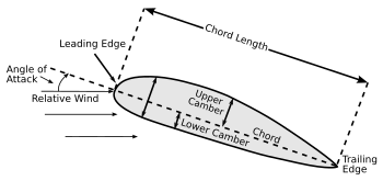
Components of the airfoil.

An airfoil (in American English) or aerofoil (in British English) is the shape of a Wing or blade (of a propeller, rotor or turbine) or sail as seen in cross-section.

An airfoil-shaped body moved through a fluid produces a force perpendicular to the motion called lift. Subsonic flight airfoils have a characteristic shape with a rounded leading edge, followed by a sharp trailing edge, often with asymmetric camber. Foils of similar function designed with water as the working fluid are called hydrofoils.

Contents

  • Introduction
  • Airfoil Terminology
  • Thin Airfoil Theory
  • Derivation Of Thin Airfoil Theory

INTRODUCTION

A fixed-wing aircraft's wings, horizontal, and vertical stabilizers are built with airfoil-shaped cross sections, as are helicopter rotor blades. Airfoils are also found in propellers, fans, Compressors and turbines. Sails are also airfoils, and the underwater surfaces of sailboats, such as the centerboard and keel, are similar in cross-section and operate on the same principles as airfoils. Swimming and flying creatures and even many plants and sessile organisms employ airfoils; common examples being bird wings, the bodies of fishes, and the shape of sand dollars. An airfoil-shaped wing can create downforce on an automobile or other motor vehicle, improving traction.

Any object with an angle of attack in a moving fluid, such as a flat plate, a building, or the deck of a bridge, will generate an aerodynamic force (called lift) perpendicular to the flow. Airfoils are more efficient lifting shapes, able to generate more lift (up to a point), and to generate lift with less drag.


Lift and Drag curves for a typical airfoil

A lift and drag curve obtained in wind tunnel testing is shown on the right. The curve represents an airfoil with a positive camber so some lift is produced at zero angle of attack. With increased angle of attack, lift increases in a roughly linear relation, called the slope of the lift curve. At about eighteen degrees this airfoil stalls and lift falls off quickly beyond that. Drag is least at a slight negative angle for this particular airfoil, and increases rapidly with higher angles. Airfoil design is a major facet of aerodynamics. Various airfoils serve different flight regimes. Asymmetric airfoils can generate lift at zero angle of attack, while a symmetric airfoil may better suit frequent inverted flight as in an aerobatic aeroplane. In the region of the ailerons and near a wingtip a symmetric airfoil can be used to increase the range of angle of attacks to avoid spin-stall. Ailerons itself are not cut into the airfoil, but extend it. Thus a large range of angles can be used without Boundary layer separation. Subsonic airfoils have a round leading edge, which is naturally insensitive to the angle of attack. For intermediate Reynold's number already before maximum thickness Boundary layer separation occurs for a circular shape, thus the curvature is reduced going from front to back and the typical wing shape is retrieved. Supersonic airfoils are much more angular in shape and can have a very sharp leading edge, which — as explained in the last sentence — is very sensitive to angle of attack. A supercritical airfoil has its maximum thickness close to the leading edge to have a lot of length to slowly shock the supersonic flow back to subsonic speeds. Generally such transonic airfoils and also the supersonic airfoils have a low camber to reduce drag divergence. Movable high-lift devices, flaps and sometimes slats, are fitted to airfoils on almost every aircraft. A trailing edge flap acts similar to an aileron, with the difference that it can be retracted partially into the wing if not used (and some flaps even make the plane a if used). A laminar flow wing has a maximum thickness in the middle camber line. Analysing the Navier-Stokes equations in the linear regime shows that a negative pressure gradient along the flow has the same effect as reducing the speed. So with the maximum camber in the middle, maintaining a laminar flow over a larger percentage of the wing at a higher cruising speed is possible. However, with rain or insects on the wing or for jetliner speeds this does not work. Since such a wing stalls more easily, this airfoil is not used on wingtips (spin-stall again).

Schemes have been devised to describe airfoils — an example is the NACA systems. Various ad-hoc naming systems are also used. An example of a general purpose airfoil that finds wide application, and predates the NACA system, is the Clark-Y. Today, airfoils are designed for specific functions using inverse design programs such as PROFOIL, XFOIL and AeroFoil. X-foil is an online program created by Mark Drela that will design and analyze subsonic isolated airfoils. Modern aircraft wings may have different airfoil sections along the wing span, each one optimized for the conditions in each section of the wing.


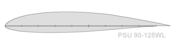
An airfoil designed for winglets (PSU 90-125WL)

AIRFOIL TERMINOLOGY

The various terms related to airfoils are defined below:

  • The mean camber line is a line drawn midway between the upper and lower surfaces.
  • The chord line is a straight line connecting the leading and trailing edges of the airfoil, at the ends of the mean camber line.
  • The chord is the length of the chord line and is the characteristic dimension of the airfoil section.
  • The maximum thickness and the location of maximum thickness are expressed as a percentage of the chord.
  • For symmetrical airfoils both mean camber line and chord line pass from centre of gravity of the airfoil and they touch at leading and trailing edge of the airfoil.
  • The aerodynamic center is the chord wise length about which the pitching moment is independent of the lift coefficient and the angle of attack.
  • The center of pressure is the chord wise location about which the pitching moment is zero.

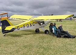
An airfoil section is displayed at the tip of this Denney Kitfox aircraft, built in 1991.

From top to bottom:
  • laminar flow airfoil for a RC park flyer;
  • laminar flow airfoil for a RC pylon racer;
  • laminar flow airfoil for a manned propeller aircraft;
  • laminar flow at a jet airliner airfoil;
  • stable airfoil used for flying wings;
  • aft loaded airfoil allowing for a large main spar and late stall;
  • transonic supercritical airfoil;
  • supersonic leading edge airfoil.

    Colours:
    Black = laminar flow,
    red = turbulent flow,
    grey = subsonic stream,
    blue = supersonic flow volume

THIN AIRFOIL THEORY

Thin airfoil theory is a simple theory of airfoils that relates angle of attack to lift. It was devised by German mathematician Max Munk and further refined by British aerodynamicist Hermann Glauert and others in the 1920s. The theory idealizes the flow around an airfoil as two-dimensional flow around a thin airfoil. It can be imagined as addressing an airfoil of zero thickness and infinite wingspan.

Thin airfoil theory was particularly notable in its day because it provided a sound theoretical basis for the following important properties of airfoils in two-dimensional flow:
(1) on a symmetric airfoil, the center of pressure lies exactly one quarter of the chord behind the leading edge
(2) on a Cambered airfoil, the aerodynamic Center lies exactly one quarter of the chord behind the leading edge
(3) the slope of the lift coefficient versus angle of attack line is 2 \pi\! units per radian

As a consequence of (3), the section lift coefficient of a symmetric airfoil of infinite wingspan is:

 \ c_L = 2\pi \alpha
where c_L\! is the section lift coefficient,
\alpha\! is the angle of attack in radians, measured relative to the chord line.

(The above expression is also applicable to a cambered airfoil where \alpha\! is the angle of attack measured relative to the zero-lift line instead of the chord line.)

Also as a consequence of (3), the section lift coefficient of a cambered airfoil of infinite wingspan is:

 \ c_L = c_{L_0} + 2\pi\alpha
where  \ c_{L_0} is the section lift coefficient when the angle of attack is zero.

Thin airfoil theory does not account for the stall of the airfoil which usually occurs at an angle of attack between 10° and 15° for typical airfoils.

DERIVATION OF THIN AIRFOIL THEORY

The airfoil is modeled as a thin lifting mean-line (camber line). The mean-line, y(x), is considered to produce a distribution of vorticity γ(s) along the line, s. By the Kutta condition, the vorticity is zero at the trailing edge. Since the airfoil is thin, x (chord position) can be used instead of s, and all angles can be approximated as small.

From the Biot-Savart law, this vorticity produces a flow field w(s) where

w(x) = \frac{1} {(2 \pi)} \int_{0}^{c} \frac {\gamma (x')}{(x-x')} dx'

where x is the location at which induced velocity is produced, x' is the location of the vortex element producing the velocity and c is the chord length of the airfoil.

Since there is no flow normal to the curved surface of the airfoil, w(x) balances that from the component of main flow V which is locally normal to the plate — the main flow is locally inclined to the plate by an angle α − dy / dx. That is

V . (\alpha - dy/dx) = w(x) = \frac{1} {(2 \pi)} \int_{0}^{c} \frac {\gamma (x')}{(x-x')} dx'

This integral equation can by solved for γ(x), after replacing x by

\ x = c(1 - cos (\theta ))/2 ,

as a Fourier series in Ansin(nθ) with a modified lead term A0(1 + cos(θ)) / sin(θ)

That is \frac{\gamma(\theta)} {(2V)} = A_0 \frac {(1+cos(\theta))} {sin(\theta)} + \sum  A_n . sin (n \theta))

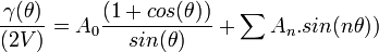
(These terms are known as the Glauret integral).

The coefficients are given by A_0 = \alpha - \frac {1}{\pi} \int_{0}^{\pi} ((dy/dx) . d\theta

and A_n = \frac {2}{\pi} \int_{0}^{\pi} cos (n \theta) (dy/dx) . d\theta

By the Kutta-Joukowski theorem, the total lift force F is proportional to

 \rho V \int_{0}^{c} \gamma (x). dx

and its moment M about the leading edge to  \rho V \int_{0}^{c} x.\gamma (x) . dx

The calculated Lift coefficient depends only on the first two terms of the Fourier series, as

 \ C_L = 2 \pi (A_0 + A_1/2)

The moment M about the leading edge depends only on A0,A1 and A2 , as

 \ C_M = - 0.5 \pi (A_0+A_1-A_2/2)

The moment about the 1/4 chord point will thus be,

 \ C_M(1/4c) = - \pi /4 (A_1 - A_2) .

From this it follows that the center of pressure is aft of the 'quarter-chord' point 0.25 c, by

 \ \Delta x /c = \pi /4 ((A_1-A_2)/C_L)

The aerodynamic center, AC, is at the quarter-chord point. The AC is where the pitching moment M' does not vary with angle of attack, i.e.

 \frac { \partial (C_{M'}) }{ \partial (C_L)} = 0


This post was posted by Pradeep.M.K, III year, Aeronautical Engineering, Hindusthan Institute Of Technology